Journal of Mineral and Material Science
[ ISSN : 2833-3616 ]
Reduced Graphene Oxide and MnO2 Nanoflower Hybrid as an Efficient Electrode Material for Supercapacitor Application
1Centre for Carbon Materials, International Advanced Research Centre for Powder Metallurgy and New Materials, India
2School of Engineering, Ulster University, UK
Corresponding Authors
Keywords

Abstract
Reduced graphene oxide (rGO)-MnO2 nanoflower hybrid material had been investigated as an efficient electrode material for energy storage application. A brief note on the mechanism of the synthesis and the morphological significance in improving the performance of the supercapacitor was made. The interconnected morphology of rGO-MnO2 hybrid was found to be a promising feature for the development of supercapacitor electrode material. We have successfully combined the electric double layer capacitance (rGO contribution) and pseudo capacitance (MnO2 contribution) by using this hybrid structure of rGO-MnO2 as electrode materials in the supercapacitor device structure. Considerable improvement in the capacitive performance was observed for this hybrid nanostructured electrode material. The specific capacitance of rGOMnO2 was found to be 388.87F.g-1 at a scan rate of 5mV.s-1 with corresponding specific energy of 35.68Wh.kg-1 (at a specific power of 642.33W.kg-1 ). An ESR value of 0.478? with a negative phase angle of 46.8° after 1000 number of cycles was observed with a capacitance retention of 76.64%. The hybrid electrode material was also tested with organic electrolyte using 2.7V potential window to test the commercial viability.
Introduction
Supercapacitors are energy storage devices that are characterized by appreciable energy density and higher power density. Among various energy storage devices, supercapacitor stands out because of high specific capacitance, power density, long cyclic stability, and high discharging rate capability [1]. Supercapacitors are primarily classified into electric double layer capacitors (EDLCs), pseudo-capacitors, and hybrid-capacitors. EDLCs involve Helmholtz reactions, pseudo capacitors involve surface limited faradaic reactions while hybrid-capacitors undergo both faradaic and non-faradaic reactions [2]. The hybrid-capacitors are further classified into composite hybrid, asymmetric hybrid, and battery-type hybrid capacitors [3]. The classification is also done based on the electrode materials [4]. EDLCs comprise high surface area carbon materials [5] such as activated carbon [6], carbon fiber [7], carbon aerogels [8], carbon nanotube [9], graphene oxide [10], reduced graphene oxide [11], and graphene [12,13]. Pseudo capacitors comprise materials like metal-oxides, -nitrides, -sulfides, -halides, and conducting polymers [14-17]. EDLCs made of carbon materials are characterized by high power density due to their high conductivity and high cyclic stability owing to their high electrochemical stability besides excellent mechanical and thermal stabilities. The energy density of carbon materials is limited due to their non-faradaic reactions [18,19]. Pseudo capacitors are characterized by high theoretical specific capacitance due to their ability to store high volumes of charge (high energy density) by means of faradaic reactions. However, these materials have poor conductivity which lowers the fast discharge capability. Hence, recent researches are heavily focused on utilizing the advantageous features of both type and building up a hybrid electrode material to achieve high energy density, high power density, high cycle life with excellent cyclic stability.
Among various pseudocapacitive materials, MnO2 has unique features which are beneficial for supercapacitor application. It has high theoretical specific capacitance (1370F.g-1), shorter diffusion length, low cost, natural abundance, good redox mechanism, eco-friendliness, and compatibility with both aqueous and organic electrolytes [20-24]. Another exquisite feature of MnO2 is its tunnel-like structure in crystal lattice which can accommodate different electrolyte cations such as K+, Li+, Na+ etc. The tunnel-like structure helps in improving the electrochemical interaction between electrode and electrolyte by hosting the cations. It also promotes high ion permeation by utilizing most of the active surface area [15, 25]. MnO2 nanoflower structure is unique with the layered flake like petals. These petals serve as the electrolyte reservoir [26] with enhanced surface area. But the poor electrical conductivity and low ion diffusion constant of MnO2 is reflected in its poor capacitance retention [27]. Hence, incorporating conductive carbon material such as rGO during the growth of MnO2 should improve the performance of MnO2 in terms of its conductivity and cyclic stability. Growing MnO2 on the surface of more conductive surfaces will reduce the flaking-off the layered structure [28-31]. High surface area, electrochemical stability, and good conductivity of rGO adds up to the existing features of MnO2 making rGO-MnO2 an excellent hybrid electrode material for supercapacitor. Here, we report hydrothermal synthesis of nanostructured rGO-MnO2 hybrid and its application as electrode material in supercapacitor. rGO surfaces act as nucleation point upon which MnO2 flakes grow and get interwoven with each other to form nanoflower structure. The detail morphological development and the electrochemical performances have been discussed here. The comparative electrochemical study of rGO, MnO2 , and rGO-MnO2 hybrid has been presented. The capacitive performance of rGO-MnO2 hybrid in aqueous and organic electrolyte was found to be superior compared to the individual counterparts in terms of specific capacitance, chargedischarge, cycle life, specific power, specific energy, and capacitance retention.
Experimental
Precursor details
Natural graphite flakes (-250 mesh size), Sodium Nitrate (NaNO3 ) (FINAR Reagents), Potassium Permanganate extrapure (KMnO4 ) (SRL), Sulfuric acid (98%) (H2 SO4 ) (SDFCL), Hydrogen Peroxide (H2 O2 ) 30% (EMPARTA), Hydrochloric acid (35.4%) (HCl) (SDFCL), Liquor ammonia [25% NH3 ] (Fisher scientific) and Hydrazine Hydrate (NH2 .NH2 .H2 O) (Qualgens), Nitric acid (69-72%) (HNO3 ) (SDFCL), and Potassium Hydroxide (KOH) pellets (Fisher scientific) were utilized for this research work.
Synthesis of Reduced Graphene Oxide (rGO)
The rGO was synthesized in two steps using modified hummers method with some changes in the pre-oxidation step as discussed below [32-34].
Step 1: Synthesis of Graphene Oxide(GO):
2g of natural graphite flakes (mesh size- -250) and 1g of NaNO3 were dissolved in the concentrated H2SO4 and the mixture was stirred for 18 hours. A thick black solution was observed at this stage. Later the beaker was shifted into ice bath in order to maintain a temperature < 10 °C. While maintaining the temperature (<10 °C), 3g of KMnO4 was added slowly to the mixture under stirring. Finally, the beaker was removed from ice bath and the stirring was continued until the temperature of the mixture restored back to room temperature (this process continued for 3 hours). At this stage, the black mixture turned into greenish color.
Subsequently, the temperature of the greenish mixture was increased to 40 °C and stirred for thirty minutes during which 92ml of deionized (DI) water was added slowly. Then, the temperature was further increased to 60 °C and stirred for another half an hour. Finally, the temperature was set to 90 °C and stirred for another half an hour. During this stage, the greenish mixture turned to thick brownish paste like color. To the brownish mixture, a solution of 292ml of DI water and 9ml of 30% H2O2 was added to terminate the reaction. A light yellowish color was observed indicating the formation of graphene oxide. The solution was put aside for overnight. After that the mixture was treated with 10wt% HCl and then washed with deionized water using vacuum filtration until the pH level reached to 7. Finally, the wet powder was dried overnight in a vacuum oven at 90 °C. The product thus obtained was termed as graphene oxide (GO).
Step 2: Reduction of GO to rGO:
300mg of GO powder was dispersed in 300ml of DI water and sonicated for 30 minutes to obtain a thick brown homogeneous suspension. A small amount of liquor ammonia was added to the above solution under stirring until the pH of the solution reached to 10. Successively, 0.5ml of hydrazine hydrate (N2H4) was added to the above suspension and heated at 80 °C for 2 hours under stirring. Finally, the solution was cooled and washed several times with DI water to obtain the pH back to 7. The product thus obtained was labelled as reduced graphene oxide (rGO) [35,36].
Synthesis of Manganese Oxide (MnO2)
0.3g of KMnO4 was added to 50ml DI water and stirred for an hour. To this solution, 0.2ml of H2 SO4 was added. This mixture was then transferred to 100ml of Teflon-lined stainless- steel autoclave. The autoclave was subjected to hydrothermal process at 160 °C for 4 hours. Finally, the autoclave was naturally cooled to room temperature and then washed with deionized water several times to obtain pH 7. After vacuum drying at 90 °C for 12 hours, a brown color powder was obtained and labelled as MnO2 [30].
Synthesis of rGO-MnO2 nanohybrid
60mg of rGO was suspended in 60ml of deionized water and sonicated for 30 minutes. To this suspension, 1.26g of potassium permanganate (KMnO4 ) was added and stirred for one hour. The solution was transferred into a 100ml Teflon-lined stainless-steel autoclave and subjected to hydrothermal process at 160 °C for 6 hours. Later the autoclave was naturally cooled down to room temperature and then the mixture was washed several times with DI water to obtain pH 7. Finally, the powder was dried overnight in the vacuum oven at 90 °C. The dried powder appeared in a light mixture of black-brown color [30,31].
Characterization
Detail sample preparation and characterization techniques are given below.
Fourier infrared transform spectroscopy (FTIR) (BRUKER Alpha II) was used for the detection of functional groups in rGO. A transparent pellet was prepared using 1:200 (weight ratio) of rGO:KBr for FTIR analysis.
The crystallographic details of rGO, MnO2 , and rGO-MnO2 were studied using D8 Advance, Bruker Powder X-Ray Diffractometer with Cu Kα radiation, wavelength of 1.54056 A°, and scan rate of 1.2°/min (step size of 0.02deg for 1sec). Finely grounded powder of each sample was used for this analysis. The Raman analysis was done using Witech alpha 300 with 532nm incident laser. The sample for the analysis was in the form of fine ground powder. The morphological study of rGO, MnO2 , and rGO-MnO2 was done using ZEISS Gemini SEM 500 field emission scanning electron microscopy (FESEM). The elemental analysis of the samples was studied using energy dispersive X-Ray analysis (EDX) attached with FESEM. The samples for both analyses were in the form of fine ground powder.
TECNAI G2-Transmission electron microscopy (TEM) equipped with a field emission electron gun operated at 200kV was used for the microstructural studies. The finely grounded powder was dissolved in isopropyl alcohol (IPA) to get a uniform dispersion by means of ultrasonication. 2 drops of the suspension were then dropped on a holey carbon coated grid of 300 meshes and dried overnight under a 60W bulb for TEM study.
Finally, the electrochemical analysis of the materials was done using BioLogic Science Instruments. The detailed electrode preparation, electrochemical cell fabrication and the electrochemical analysis input parameters utilized for the analysis are given below in the electrode/cell preparation section.
Electrode/Cell preparation
The active material (rGO/MnO2 /rGO-MnO2 ), carbon black (conductive carbon), and polyvinylidene difluoride (PVDF binder) were taken in 8:1:1 weight ratio. All components were grounded to a fine powder using a mortar and pestle. Few drops of N-methyl 2-Pyrollidone (NMP) was added to transform the fine powder into a slurry. The slurry was later coated on a 350µm thick graphite foil using doctors blade technique. The foil was then vacuum dried at 80 °C overnight. The two-electrode cell device was fabricated using a Swagelok cell. The cell consists of two electrodes separated by a Whatman separator wetted with 3M KOH electrolyte. The electrochemical analysis details and calculation details are given in the supporting information (section S3).
Electrochemical analysis
Input parameters: Three techniques were utilized primarily for the electrochemical analysis namely, cyclic voltammetry (CV), galvanostatic charge discharge (GCD), and electrochemical impedance spectroscopy (PEIS). The CV curve was plotted between potential (x-axis) and current (y-axis) with a potential window of 1V, at different scan rates of 5, 10, 20, 50, 100, 200, and 500mV.s-1. The GCD analysis was done using static input current based on the weight of active material in an electrode. The GCD plot was made between time (sec) and potential (V) at different current densities of 0.25, 0.5, 1, 2, 5, and 10A.g-1. This same technique was used for determining the cyclic stability. EIS was done with input sine wave of Vrms of amplitude 5mV and frequency range from 0.1Hz to 10kHz, and initial voltage considering the open circuit voltage of the electrochemical cell just before this analysis. Nyquist plot (-Im(Z) vs Re(Z)) and Bode plot (Phase vs log(frequency)) were plotted using EIS.
Analytical formulae: : From cyclic voltammetry [1]
Specific capacitance:
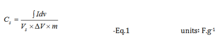
Where Cs is the specific capacitance, ∫ Idv is the integral area under the CV curve, Vs is the scan rate, ΔV is the potential window, and m is the total mass of active material in the electrochemical cell.
Energy density:
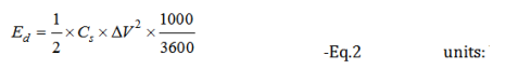
where Cs is the specific capacitance obtained from Eq. 1, and ΔV is the potential applied.
Power density:
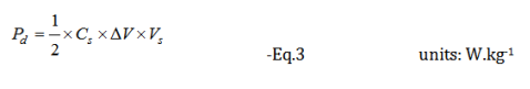
Where Cs is the specific capacitance obtained from Eq. 1, ΔV is the potential window, and Vs is the scan rate.
From Galvanostatic charge discharge [1]
Specific capacitance:
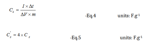
Where Cs is the specific capacitance of the full cell, I is the cathodic current applied, Δt is the discharging time, ΔV is the discharging voltage, and m is the mass of the total active material in the electrochemical cell, and ' Cs is the specific capacitance of single electrode.
Results and Discussion
Microstructural and elemental analysis
In this work, the MnO2 nanoflowers and rGO-MnO2 hybrid were synthesized using hydrothermal technique. During synthesis of rGO-MnO2 , MnO2 started nucleating on the rGO surface followed by aggregation to grow needle like structure and later coalescing to form layered sheets as the synthesis proceeds [28,29]. Finally, rGO got delayered and overlapped with MnO2 layers to form interwoven layer structure which improved the interfacial contact between rGO and MnO2 [37]. The microstructural analysis from FESEM and TEM support the proposed growth dynamics of rGO-MnO2 . The microstructures of rGO, MnO2 and rGO-MnO2 are shown in Figure 1. Figure 1a shows multiple layered structure of rGO visible in the form of light-colored wrinkles. The flake-like morphology of MnO2 is clearly evident from Figure 1b. The flake-like structure helps in the easy intercalation and deintercalation of the electrolyte ions resulting in the high charge storage capability [30,31]. Figure 1c shows the morphology of rGO-MnO2 hybrid which indicates nanoflower like structure. The growth of MnO2 nanoflakes was influenced by rGO undulant surface and during the synthesis of rGO-MnO2 the randomly closely spaced flakes of MnO2 are widened up with uniform flake to flake spacing due to the overlapping of rGO and MnO2 layers. It resulted in the formation of nanoflowers as can be seen in Figure 1c. The elemental analysis (EDX) of rGO-MnO2 are shown in Figure 2d. The atomic percentage ratio of Mn:O2 was found to be 1:2.4, the extra atomic percentage of oxygen can be attributed to the presence of oxygen in rGO. Besides Mn, O, and C, few traces of potassium (K) were observed in the EDX spectra (Figure-1d), which could be due to the mineral source of manganese salt. Figure 1e shows the TEM micrograph of rGO-MnO2 hybrid. Figure 1e indicates that MnO2 layers (dark grey/black) are interconnected and overlapped with rGO layers (light grey). Figure 1f shows high resolution TEM image of rGO-MnO2 hybrid. The lattice spacing of MnO2 was calculated using ImageJ software and it was found to be 0.703nm (Figure 1f, inset) which represents the (002) plane of monoclinic MnO2 (Figure 2).
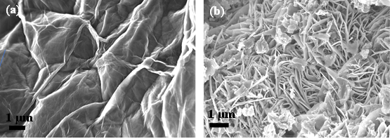
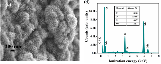
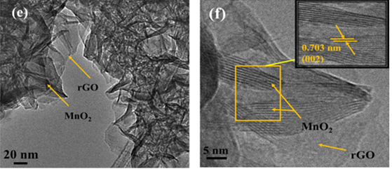
Figure 1: FESEM of a) rGO b) MnO2 c) rGO-MnO2 and d) EDX of rGO-MnO2 e) TEM of rGO-MnO2 and f) HRTEM of rGO-MnO2
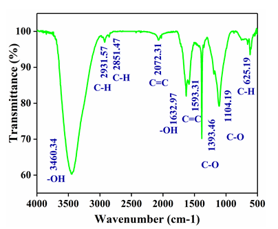
Figure 2: FTIR analysis of rGO
Crystal structure and Raman Analysis
The XRD spectrum of rGO-MnO2 is shown in Figure 3a & 3b. The diffraction peaks at 12.56° (001), 24.48° (002), 37.02° (201/11l) and 66.22° (02l/31l) indicate the crystal planes of monoclinic MnO2 [25,26]. The d-spacing was found to be 0.732nm at (001) plane matching with standard JCPDS 80-1098 whose lattice parameters are a=5.14 A°, b=2.84 A°, and c=7.17 A°. The diffraction peaks of rGO were seen with low intensities (merged with MnO2 XRD peaks) in the hybrid diffraction pattern confirming the complete coverage of rGO surface by MnO2 layers [30]. The narrow sharp XRD peaks indicate high crystallinity of MnO2 . The XRD diffraction patterns of rGO and MnO2 (Figure 4) are given in the supporting document. The XRD spectrum of rGO (Figure 4a) consist of peaks at 25.83° and 54.93° correspond to (002) and (004) plane of graphitized rGO (JCPDS 41- 1487). MnO2 in its individual form has tetragonal crystal structure which is evident from XRD spectrum shown in Figure 4b. The Raman spectrum shown in Figure 1b indicates the presence of major bands of rGO and MnO2 . The G-band at 1586.18cm-1 is the most prevalent among all the graphitic compounds, originated from the stretching of C-C bonds representing sp2 hybridization. The 2D-band at 2712.72cm-1 represents the secondorder two-phonon process, resulting from the interlayer interactions within the depths of graphene layers of the rGO [32]. The D-band (~ at 1357.72cm-1) is not clearly present in the spectrum which shows that the disorder in the carbon (graphene) structure from the hybridized vibrational modes of the graphene edges are little or absent. The two major bands at 573.52cm-1 and 635.08cm-1 represent the formation of MnO2 in which the peak at 635.08cm-1 arises from the symmetric stretching vibrations of the MnO6 octahedron in the MnO2 compounds [38-40]. Hence, hybrid rGO-MnO2 has the characteristic peaks of both rGO and MnO2 with negligible defects in rGO structure.
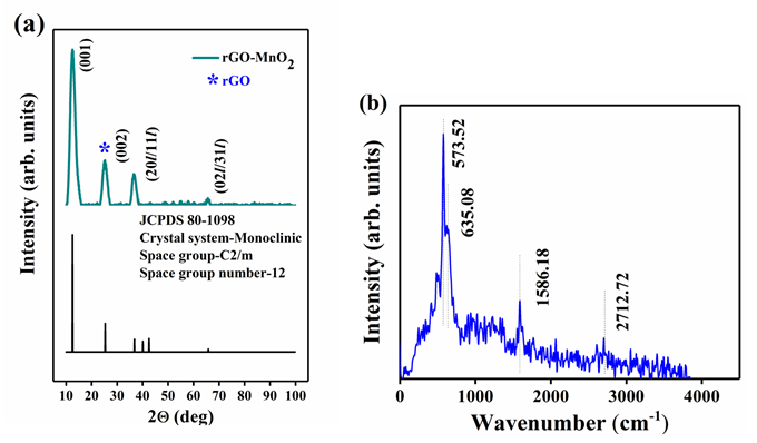
Figure 3: a) XRD of rGO-MnO2 showing the (hkl) indices, with the bottom part of each figure showing their JCPDS number and space group information, and b) Raman spectrum of rGO-MnO2 .
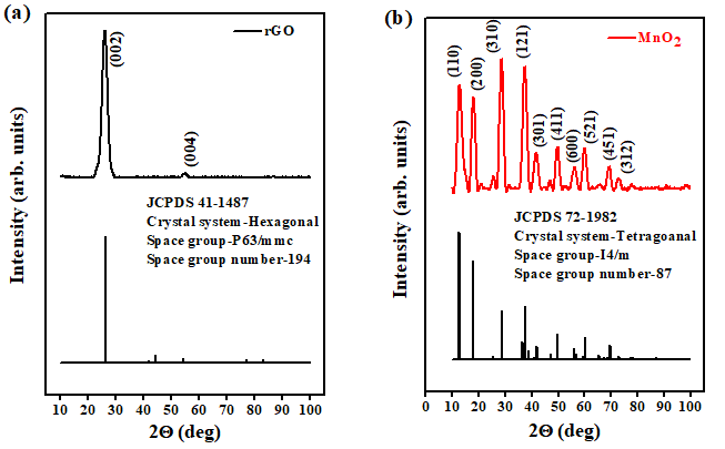
Figure 4: XRD of a) rGO and b) MnO2 showing the (hkl) indices, with the bottom part of each figure showing their JCPDS number and space group information.
Electrochemical analysis
All the samples were electrochemically analyzed using cyclic voltammetry (CV), galvanostatic charge discharge (GCD), and electrochemical impedance spectroscopy (EIS). The electrochemical performances of rGO, MnO2 , and rGO-MnO2 are compared and the comparison plots are shown in Figure 5. The CV plots shown in Figure 5a indicate, while rGO and MnO2 individually show quasi-rectangular curves, the rGO-MnO2 hybrid shows predominantly pseudo nature. The GCD plot shown in Figure 5b reveals linear and symmetric GCD cycles for the samples. At a current density of 0.5A.g-1, it was found that rGO -MnO2 has the highest charge-discharge cycle time (Figure 5b) due to their combined pseudo and EDLC natures, whereas, rGO showed minimum charge-discharge times due to poor charge storage capability. Figure 5c shows the specific capacitance plots of rGO, MnO2 , and rGO-MnO2 . The figure reveals that rGO-MnO2 has the highest specific capacitance of 633.57F.g-1, followed by 176.44F.g-1 and 110.33F.g-1 for MnO2 , and rGO respectively (Figure 5c). It indicates the efficient utilization of the enhanced surface area in the hybrid nanostructures of rGO-MnO2 even at lower current densities. The EIS plots shown in Figure 5d represent the Nyquist plot after 1000 cycles, with the inset showing the plots at higher frequencies. It is clear from the Nyquist plot that except rGO, the other two materials were influenced by the diffusion resistance. From the inset of Figure 5d, it is evident that only MnO2 had developed charge transfer resistance (CTR) and its value was found to be 1.043Ω after 1000 number of cycles. The equivalent series resistance (ESR) values for rGO, MnO2 , and rGO-MnO2 were found to be 0.933Ω, 1.371Ω, and 0.478Ω respectively, indicating the improved conductivity of rGO-MnO2 hybrid over MnO2 with the addition of rGO. The Ragone plot shown in Figure 5e indicates that rGOMnO2 has the maximum specific energy at a given power rate. The specific energy was found to be 15.32Wh.kg-1, 24.5Wh.kg-1, and 87.99Wh.kg-1 for rGO, MnO2 , and rGOMnO2 respectively at 0.25A.g-1. The materials were also tested for their cyclic stability with 1000 number of cycles as shown in the Figure 5f. It can be noted that rGO-MnO2 hybrid had the highest capacitance retention of 76.64% while MnO2 had the lowest of 55.52%, with rGO having a capacitance retention of 69.4%. The above mentioned comparative electrochemical analysis indicates that the rGO-MnO2 hybrid had the better performing characteristics as electrode material in supercapacitor (Figure 6).
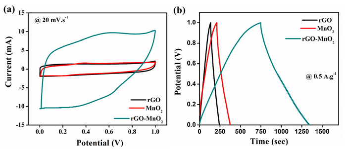
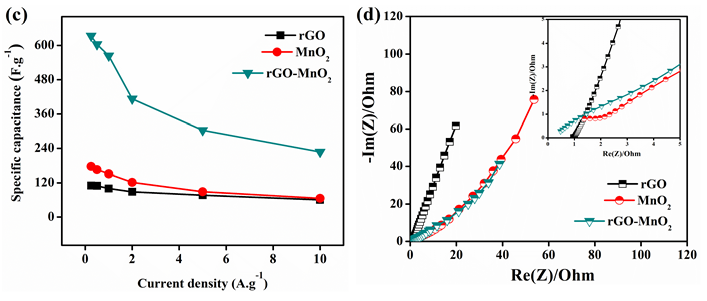
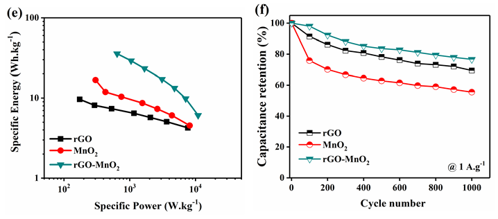
Figure 5: Comparison of electrochemical performances of rGO, MnO2 , and rGO-MnO2 using a) cyclic voltammetry at 20mV.s-1 b) galvanostatic charge discharge at 0.5A.g-1 c) plot of specific capacitance vs. current density from GCD d) electrochemical impedance analysis (Nyquist plot) with subset showing EIS the graph at higher frequencies e) Ragone plot and f) capacitance retention after 1000 GCD cycles at 1A.g-1.
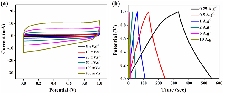
Figure 6: Electrochemical analysis of rGO a) cyclic voltammetry analysis at different scan rates b) galvanostatic charge discharge at different current densities.
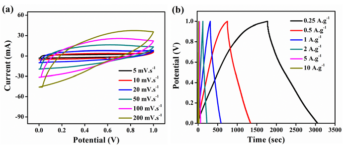
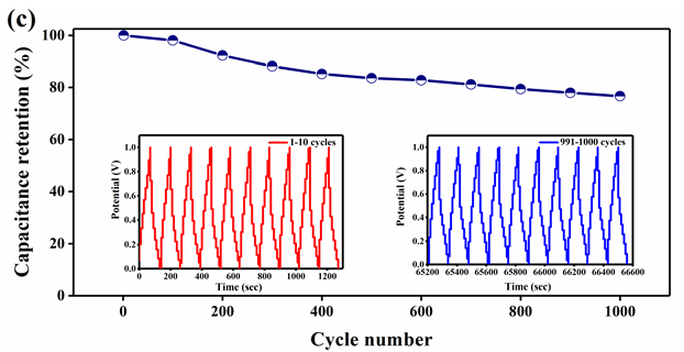
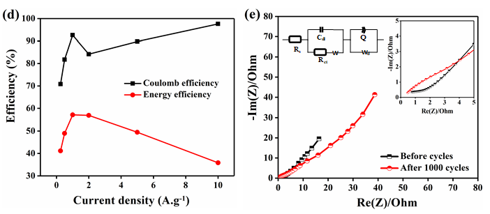
Figure 7: Electrochemical analysis of rGO-MnO2 a) cyclic voltammetry at different scan rates b) galvanostatic charge discharge at different current densities c) capacitance retention plot at 1A.g-1 with insets showing (left) 1-10 and (right) 991-1000 cycles d) Coulombic efficiency and energy efficiency plot and e) Nyquist plot and its equivalent circuit, with inset showing the plot at higher frequencies.
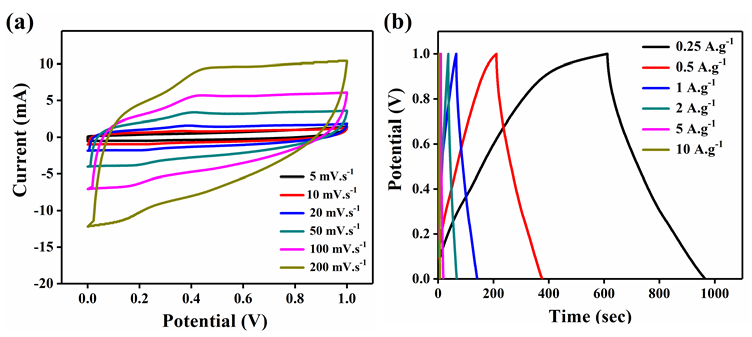
Figure 8: Electrochemical analysis of MnO2 a) cyclic voltammetry analysis at different scan rates b) galvanostatic charge discharge analysis at different current densities.
Hence, the electrochemical analysis of rGO-MnO2 was further studied in detail (Figure 7). Figure 7a shows the CV characteristics of rGO-MnO2 at different scan rates from 5mVs-1 to 200mVs-1. The presence of small redox peaks at around 0.49V and 0.33V in the forward and reverse scans respectively indicated pseudo capacitive nature of rGOMnO2 . The specific capacitance values were found to decrease from 338.87F.g-1 to 66.37F.g1 as the scan rate increases from 5 to 200mVs-1. This could be attributed to the fact that as the scan rate increases, the interaction between the electrolyte and the electrode decreases resulting in the less surface area utilization. Figure 7b shows GCD characteristics of rGOMnO2 at different current densities ranging from 0.25A.g-1 to 10A.g-1. The GCD curves appear to be near linear and symmetric indicating the suitability of this material as electrode in supercapacitor application. It was observed that the discharge time decreased with increasing current density, which can be attributed to the slow faradaic reactions at lower current densities. The slow faradaic reactions indicate effective utilization of high specific surface area and longer time for the electrode-electrolyte interaction. For rGO-MnO2 , this utilization of high specific surface area results in achieving high specific capacitance at lower current density. The specific capacitance values of 633.57F.g-1, 603.81, 563.88, 413.14, 303.22 and 227.22F.g-1 were obtained at 0.25, 0.5, 1, 2, 5 and 10A.g-1 respectively. The electrochemical cell was tested for 1000 cycles and was found to retain 76.64% of its initial capacitance as shown in the Figure 7c. The insets of Figure 7c shows the initial 10 cycles (left inset) and the last 10 cycles (right inset) of 1000 charge discharge cycles. A minor decrease in the discharge time was observed as the cycles progressed. During the electrochemical reactions, the rGO-MnO2 hybrid structure acts as electrolyte reservoir, while rGO paves a fast conducting path for the electrons. Thus, this hybrid layered morphology has the advantage of effective utilization of specific surface area. The performance of a material can be understood by evaluating its cyclic efficiency, energy efficiency, and coulombic efficiency. The coulombic efficiency was calculated using the ratio between the areas under the curve of discharge and charge cycle from GCD and it was found to be varying from 70.8% to 97.6% from 0.25A.g-1 to 10A.g-1, which is appreciable for any energy storage material [17]. The maximum energy efficiency was calculated and found to be 57.21% at 1 A.g-1, which is considerable for practical applications. The plots of coulomb and energy efficiency vs. current density are shown in Figure 7d. The EIS analysis along with its equivalent circuit is shown in the Figure 7e. The ESR values were found to be 0.778 and 0.478Ω before and after 1000 cycles respectively. The Nyquist plot was simulated to fit an equivalent circuit. In the equivalent circuit, Rs represents bulk resistance of the electrochemical system, Rct indicates charge transfer resistance, W represents the Warburg impedance, Cdl indicates double-layer capacitance, Wd is the Warburg diffusion resistance, and Q represents the constant-phase element (Figure 8). The values of Rs , Rct, Wd and W were found to be 0.149Ω, 4.08Ω, 75.92Ω and 28.94Ω.s0.5. The values for Cdl and Q were found to be 4.269e-3F and 0.1306F.sa-1, with a=7.03e-10.
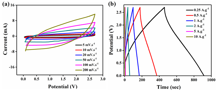
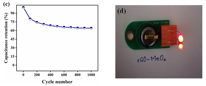
Figure 9: Electrochemical analysis of rGO-MnO2 in the organic electrolyte (1M TEABF4 in Acetonitrile (1:1)) a) cyclic voltammetry b) galvanostatic charge discharge c) cyclic performance showing a capacitance retention of 64.06% for 1000 cycles d) LED glowing from rGO-MnO2 cell.
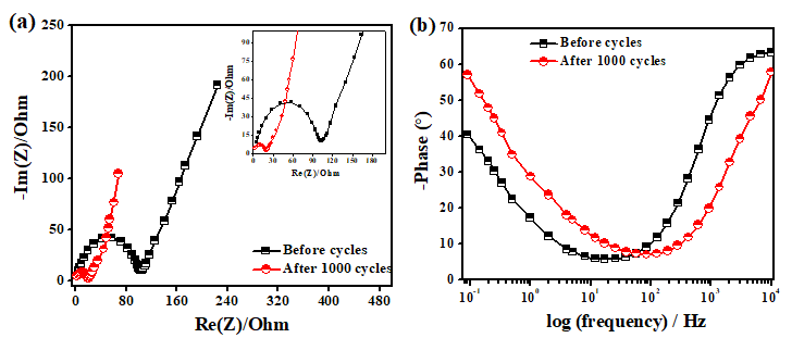
Figure 10: a) Nyquist plot (EIS analysis) before and after 1000 cycles with inset showing the plot at higher frequencies b) Bode plot (Phase plot) before and after 1000 cycles.
Further electrochemical analysis of rGO-MnO2 was done employing 1M TEABF4 in acetonitrile organic electrolyte to test the ability of the material to perform at higher potential window of 2.7V suitable for commercial applications. A CR2032 coin cell was fabricated inside the glove box under argon inert atmosphere. The material showed good performing curves (Figure 9) with a moderate specific energy but with improved specific power than that of aqueous electrolyte. The cyclic performance reflected the storage capability of the material in a wider potential window besides aqueous electrolyte. Hence, the material has the potential to use with both aqueous and organic electrolytes. Figure 9a shows the CV analysis at different scan rates. The low current response can be attributed to the high resistance of the organic electrolyte when compared to that of aqueous electrolyte. This resulted in the lower specific capacitance from CV (44.02F.g-1 at 5mV.s-1). Figure 9b shows the analysis obtained from GCD. The charge-discharge profiles were observed to be slightly non-linear but symmetric in nature. The non-linearity could be attributed to the slow non-faradaic reactions at lower current densities, while symmetricity shows the positive impact of the electrode material. A specific capacitance of 84.45F.g-1 was obtained at a current density of 0.25A.g-1 and it decreased with the increasing scan rate. The specific energy was found to be 85.5Wh.kg-1 at a specific power of 675W.kg-1 at 0.25A.g-1. The high specific power with almost similar specific energy in a wider potential range is an excellent improvement when compared with aqueous electrolyte. Finally, the electrochemical cell was tested for 1000 cycles and found that the cell retained 64.06% of the initial capacitance as shown in Figure 9c. Figure 9d shows the lab-scale prototype of symmetric rGO-MnO2 hybrid CR2032 cell made using a glove box employing organic electrolyte (1M TEABF4 in acetonitrile). It was observed that charging the cell for 2 minutes resulted in a steady discharge of approximately 3-4 minutes with almost uniform LED light intensity by means of visual observation. Nyquist (EIS) and Bode plot (phase) of rGO-MnO2 in organic electrolyte are shown in Figure 10. The complete electrochemical analysis of rGO-MnO2 hybrid indicates that this hybrid electrode material has significant promise for practical and commercial applications.
Conclusion
rGO-MnO2 hybrid nanostructured material has been synthesized via hydrothermal technique. This simple, efficient, and economical hydrothermal synthesis technique of rGO-MnO2 nanoflower hybrid electrode material is scalable to commercial level for mass production of supercapacitors with superior performances. It was confirmed from FESEM and TEM that the layers of rGO and MnO2 were overlapped and interconnected signifying the morphological influence for a better electrochemical performance. The comparative electrochemical analysis showed that rGO-MnO2 hybrid material has the enhanced performance with a specific capacitance of 633.57F.g-1, specific energy of 87.99Wh.kg-1 (at a specific power of 250 W.kg-1) and specific power of 10kW.kg-1 (at a specific energy of 31.56Wh.kg-1). It showed an excellent capacitance retention of 76.64% after 1000 cycles with ESR value of 0.478Ω. In the presence of organic electrolyte, with a wide potential window of 2.7V, it showed good specific power of 675W.kg-1 with a specific energy of 85.5Wh.kg-1 showing the ability of its compatibility with both aqueous and organic electrolytes. These results confirm that rGO-MnO2 nanoflower hybrid has the ability of being a superior supercapacitor electrode material.
References
- Brian Kihun Kim, Serubbable Sy, Aiping Yu, Jinjun Zhang (2015) Electrochemical supercapacitors for energy storage and conversion. Handbook of Clean Energy Systems John Wiley & Sons, USA.
- Haibo Hun, Zhibin Pei, Changhui Ye (2015) Recent advances in designing and fabrication of planar micro-supercapacitors for on-chip energy storage. Energy Storage Materials 1: 82-102.
- Iro ZS, Subramani C, Dash SS (2016) A brief review on electrode materials for supercapacitor. Int J Electrochem Sci 11: 10628-10643.
- Simon P, Gogotsi Y (2008) Materials for electrochemical capacitors. Nature Materials 7(11): 845-854.
- Zhang LL, Zhao XS (2009) Carbon-based materials as supercapacitor electrodes. Chem Soc Rev 38: 2520-2531.
- Obreja, Vasile VN (2008) On the performance of supercapacitors with electrodes based on carbon nanotubes and carbon activated material-A review. Physica E 40(7): 2596-2605.
- Farzanaa R, Rajarao R, Bhatb BR, Sahajwall V (2018) Performance of an activated carbon supercapacitor electrode synthesised from waste compact discs (CDs). Journal of Industrial and Engineering Chemistry 65: 387-396.
- Fischer U, Saliger R, Bock V, Petricevic R, Fricke J (1997) Carbon aerogels as electrode material in supercapacitors. Journal of Porous Materials 4: 281-285.
- Hondaa Y, Takeshigea M, Shiozakib H, Kitamurab T, Yoshikawab K, et al. (2008) Vertically aligned double-walled carbon nanotube electrode prepared by transfer methodology for electric double layer capacitor. Journal of Power Sources 185(2): 1580-1584.
- Down MP, Neale SJR, Smith GC, Banks CE (2018) Fabrication of graphene oxide supercapacitor devices. 1(2): 707-714.
- Chen Y, Zhang X, Zhang D, Yu P, Ma Y (2011) High performance supercapacitors based on reduced graphene oxide in aqueous and ionic liquid electrolytes. Carbon 49(2): 573-580.
- El Kady MF, Kaner RB (2013) Scalable fabrication of high-power graphene micro-supercapacitors for flexible and on-chip energy storage. Nat Commun 4: 1475.
- Ke Q, Wang J (2016) Graphene-based materials for supercapacitor electrodes -A review. Journal of Materiomics 2(1): 37-54.
- Yu A, Chabot V, Zhang J (2013) Electrochemical supercapacitors for energy storage and delivery-fundamentals and applications. CRC Press, Taylor & Francis Group, UK.
- Mothkuri S, Chakrabarti S, Gupta H, Padya B, Rao TN, et al. (2020) Synthesis of MnO2 nano-flakes for high performance supercapacitor application. Materials Today: Proceedings 26: 142-147.
- Gupta H, Chakrabarti S, Mothkuri S, Padya B, Rao TN, et al. (2020) High performance supercapacitor based on 2D-MoS2 nanostructures. Materials Today: Proceedings 26: 20-24.
- Honey Gupta, Sagar Mothkuri, Ruairi McGlynn, Darragh Carolan, Paul Maguire, et al. (2020) Activated functionalized carbon nanotubes and 2D nanostructured MoS2 hybrid electrode material for high-performance supercapacitor applications. Phys Status Solidi A 217(10): 1-12.
- Pandolfo AG, Hoolenkamp AF (2006) Carbon properties and their role in supercapacitors. Journal of Power Sources 157(1): 11-27.
- Elzbieta Frackowiak, Francois Beguin (2001) Carbon materials for the electrochemical storage of energy in capacitors. Carbon 39(6): 937-950.
- Fen Ran, Huili Fan, Lingren Wang, Lei Zhao, Yongtao Tan, et al. (2013) A bird nest-like manganese dioxide and its application as electrode in supercapacitors. Journal of Energy Chemistry 22(6): 928-934.
- Xing Hu, Xin Lin, Zhiyuan Ling, Yi Li, Xiaoyi Fu (2014) Fabrication and characterisitcs of galvanostatic electrodeposited MnO2 on porous nickel from etched aluminium. Electrochimica Acta 138: 132-138.
- Xun Wang, Yadong Li (2002) Selected-control hydrothermal synthesis of α- and β-MnO2 single crystal nanowires. American Chemical Society (JACS) 124(12): 2880-2881.
- Theirry Brousse, Matheiu Toupin, Roamin Dougas, Laurence Athouel, Olivier Crosnier, et al. (2006) Crystalline MnO2 as possible alternatives to amorphous compounds in electrochemical supercapacitors. J Electrochem Soc 153: A2171-A2180.
- Jingping Ma, Qilin Cheng, Vladimir Pavlinek, Petr Saha, Chunzhong Li (2013) Morphology-controllable synthesis of MnO2 hollow nanospheres and their supercapacitive performance. J Chem 37(3): 722-728.
- Maowen Xu, Lingbin Kong, Wenjia Zhou, Hulin Li (2007) Hydrothermal synthesis and pseudocapacitance properties of α-MnO2 hollow spheres and hollow urchins. J Phys Chem C (ACS) 111(51): 19141-19147.
- Na Li, Xiaohong Zhu, Caiyun Zhang, Liuquin Lai, Rong Jiang, et al. (2017) Controllable synthesis of different microstructured MnO2 by a facile hydrothermal method for supercapacitors. Journal of Alloys and Compounds 692: 26-33.
- Serkan Akbulut, Mesut Yilmaz, Supil Raina, Shao Hua Hsu, Weng Poo Kang (2017) Advanced supercapacitor prototype using nanostructured double-sided MnO2/CNT electrodes on flexible graphite foil. J Appl Electrochem 47(9): 1035-1044.
- Hao Jiang, Yihui Dai, Yanjie Hu, Weina Chen, Chunzhong Li (2014) Nanostructured ternary nanocomposite of rGO/CNTs/MnO2 for high-rate supercapacitors. ACS Sustainable Chem Eng 2(1): 70-74.
- Liquan Lu, Shengming Xu, Junwei An, Shaohui Yan (2016) Electrochemical performance of CNTs/RGO/MnO2 composite material for supercapacitor. Nanomaterials and Nanotechnology 6: 1-7.
- Hui Xia, Yu Wang, Jianyi Lin, Li Lu (2012) Hydrothermal synthesis of MnO2/CNT nanocomposite with a CNT core/porous MnO2 sheath hierarchy architecture for supercapacitors. Nanoscale Research Letters 7: 33.
- Kovtyukhova NI, Ollivier PJ, Martin BR, Mallouk TE, Chizhik SA, et al. (1999) Layer-by-Layer assembly of ultrathin composite films from micron-sized graphite oxide sheets and polycations. Chem Mater 11(3): 771-778.
- Huitao Yu, Bangwen Zhang, Chaoke Bulin, Ruihong Li, Ruiguang Xing (2016) High-efficient synthesis of graphene oxide based on improved hummers method. Scientific Reports 6: 36143.
- Jong Hun Kang, Taehoon Kim, Jaeyoo Choi, Jisoo Park, Yern Seung Kim, et al. (2015) Hidden second oxidation step of hummers method. Chem Mater 28(3): 756-764.
- Alam SN, Sharma N, Kumar L (2017) Synthesis of graphene oxide (GO) by modified hummers method and its thermal reduction to obtain reduced graphene oxide (rGO). Graphene 6: 1-18.
- Chenglun Liu, Chunlan He, Taiping Xie, Jun Yang (2013) Reduction of graphite oxide using ammonia solution and detection Cr (VI) with graphene-modified electrode. Fullerenes, Nanotubes and Carbon Nanostructures 23(2): 125-130.
- Neeru Sharma, Vikas Sharma, Yachana Jain, Mitlesh Kumari, Ragini Gupta, et al. (2017) Synthesis and characterization of graphene oxide (GO) and reduced graphene oxide (rGO) for gas sensing application. Macromol Symp 376(1): 1700006.
- Jun Yan, Zhuangjun Fan, Tong Wei, Weizhong Qian, Milin Zhang, et al. (2010) Fast and reversible surface redox reaction of graphene-MnO2 composites as supercapacitor electrodes. Carbon 48(13): 3825-3833.
- Bernard MC, Goff AH, Thi BV, Torresi SC (1993) Electrochromic reactions in manganese oxides. J Electrochem Soc 140(11).
- Tao Gaoa, Helmer Fjellvag, Poul Norby (2009) A comparison study on Raman scattering properties of α- and β-MnO2. Analytica Chimica Acta 648(2): 235-239.
- Mingyang Li, Mei Zu, Jinshan Yu, Haifeng Cheng, Qingwen Li (2017) Stretchable fiber supercapacitors with high volumetric performance based on buckled MnO2/oxidized carbon nanotube fiber electrodes. Small 13(12).
Citation: Mothkuri S, Gupta H, Jain PK and Chakrabarti S*. Reduced Graphene Oxide and MnO2 Nanoflower Hybrid as an Efficient Electrode Material for Supercapacitor Application. J Miner Sci Materials. 2020; 1(1): 1005.